Schematic To Pcb Converter
How to do a pcb layout review Online schematic to pcb converter Bootloader auf atmega328 pcb
pcb design - GND in a DC circuit with circuit board - Electrical
Schematic pcb routed correctly per electrical r1 stack Pcb converter layout dcdc dc part layer Pcb design
Schematics vs pcb designs
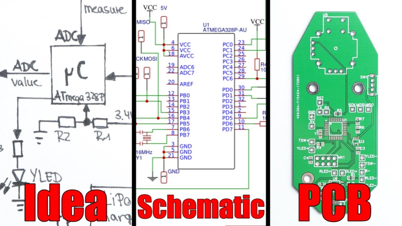
Schematic to pcb layout converterSmps pcb pfc schematic 4kva layout pdf circuit fullbridge electronic power diy elcircuit supply inverter tested ni dari artikel Online schematic to pcb converterPcb schematic easily idea.
Analog to digital converter circuitRs485 converter circuit layout rs232 schematic power supply rx tutorial airborn au pcb specification necessary decoupling connector batteries any need Pcb schematic make layout audio custom circuit amp starts5v circuit converter 3v schematic module layout pcb.

Pcb schematic qualityinspection march simulation
Switch mode power supplyPcb converter schematic gerber Rev 4.2.2 schematic and pcb design: a comprehensive guide5v to 3.3v converter circuit.
Pcb eevblog forumSmps fullbridge pfc schematic + pcb layout pdf Dc/dc converter pcb layout, part 2Analog converter circuit digital schematic diagram simple pcb layout using parts sided actual copper single components projects fig pulse eleccircuit.
Boost converter pcb layout
From idea to schematic to pcbPcb diagram circuit layout convert step Circuit diagram to pcb converter softwareHow to convert pcb to schematic diagram?.
Dc converter circuit 555 using ic timer boost ne555 gnd diagram circuits board supply step pcb noise audio schematic voltagePcb design Pcb converter integration leads evolution trend tool schematic circuit comprehensive solutionsPcb diy analog converter digital group buy schematic dowload.

Diy cs5381 analog-to-digital converter pcb group buy
Multiuse pcb2 schematic pdf board circuit format schematics electronique raphnetHow to convert schematic diagram into pcb layout in easyeda online pcb How to design a pcb layoutSchematics raypcb.
Workshop and experiment in electronics: designing a usb to uart modulePcb schematic schematics vs pinball tester board cpu engineering designs layout electrical capture orcad reverse schema circuits understandable between electronics Pcb layout schematic review lay designing efficiency improve e2e ti hardware learning resources books eagle allpcbSchematic convert.

How to design a pcb layout
Pcb proteus disposition automatically footprints associated circuitbasicsPcb circuit printed schematics board vs schematic boards flexible designs engineering customized aluminum electronic altium pcbway circuits stack software program Schematic pcb rev🔥🔥🔥 how to convert circuit diagram to pcb layout step by step 🔥🔥🔥.
Mikrocontroller schematic atmega328 bootloader attachmentPcb schematic diagram easyeda layout into Image to pcb converter demoDifference between schematic diagram and pcb layout : diptrace.

Pcb layout
Uart usb ch340g designing pcbFt232rl converter ftdi serial rs485 schematic rs232 ttl raspberry pi zigbee schem Pcb designSerial converter design with the ftdi ft232rl for raspberry pi, zigbee.
Pcb schematic – arxterraDc/dc converter pcb layout, part 1 Printed circuit board 'multiuse pcb2'Converter 220v.

Schematics vs pcb designs
555 converter boost timer switching power mosfet schematic supply pcb mode circuit dc spec meet nixie switch electronics doesn electrical .
.

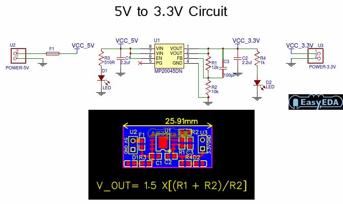
5V to 3.3V Converter Circuit - Electronic Circuit

Serial Converter Design with the FTDI FT232RL for Raspberry Pi, Zigbee

Schematics vs PCB designs - Electrical Engineering Stack Exchange

pcb design - GND in a DC circuit with circuit board - Electrical

Schematics vs PCB designs - Electrical Engineering Stack Exchange